Cost-Effective Low-Voltage DC Barrier Gates: Efficient Access
Control Easy Installation & Maintenance
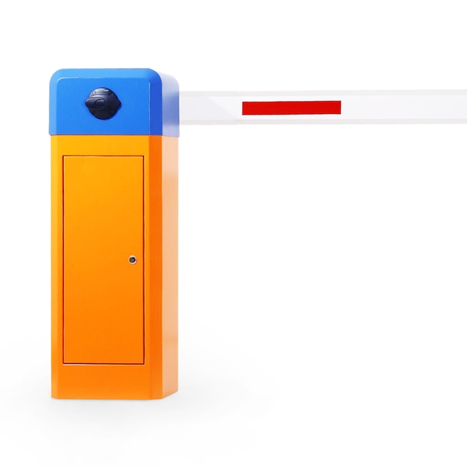
As a solution for vehicle access management, BRDC-110 DC road gates
are widely used in parking lots, neighborhoods, industrial parks
and other places. Its stability, reliability and automation
features make it an important part of modern traffic management
systems.BRDC-110 DC road gates can realize automated management through a
variety of control methods:Remote control: switch control through remote control, convenient
for remote operation.
Auto-sensing: Automatically open the gate after detecting the
vehicle through sensors (such as infrared, ground sensors, etc.).
License plate recognition: Automatically open the gate by
recognizing the license plate information of vehicles.
Control Board Wiring Diagram

- Note: it is best to use BVR wire, do not use network wire
Left And Right Split Wiring Diagram Of Barrier

Left and right split wiring diagram of the barrierConnection Method Of Common Cathode And Common Anode Of Traffic Light

Figure 2 The wiring diagram of common cathode and common anode of traffic lightProduct Performance Characteristics- The movement adopts side mounting type, easy installation and
compact structure.
- The main body of the movement is made of aluminum alloy,
manufactured by die-casting process, with reliable mechanical strength, beautiful appearance, precise size and good
heat dissipation.
The movement adopts gear reduction transmission, high transmission
efficiency, small loss of power output; gear material SCM421, carburizing heat treatment process, precision
grinding processing, anti-wear, impact resistance, service life far
exceeds the worm gear transmission structure.
The movement adopts DC brushless motor, with large output torque
and small size, and the speed can be adjusted arbitrarily through the controller, and the deceleration buffer can
be realized when dropping and lifting the pole into place, so that
the gate pole can be put into place smoothly.
The motor adopts DC24V safety voltage, which avoids the electric
shock accident caused by leakage, and provides more protection for personal safety.
Internal Dimensions

Movement Outline Picture

Motor Lead Wire Definition

Working Environment
Storage Environment
The movement should be stored in a dry and ventilated warehouse,
and the suitable temperature in the warehouse should be kept within the range of 5℃~35℃. The appropriate
temperature in the warehouse should be kept within the range of
5℃~35℃, the relative humidity should not be higher than 65, and
harmful gases, vapors and dust should be prevented from intruding.Operating Life
The movement has a working life of ≥5 million cycles within the
range of normal gate length and speed.Gate Pole Mounting Plate-Octagonal Pole


Barrier Commissioning Steps
Step 1: Match The Rod And Spring
Stop the gate lever at about 45 degrees and check whether the lever
will slowly drop or open the gate (if the gate is opened, explain the spring tension is too large (the rod is
allowed to open the brake slowly if the spring tension is slightly
larger). If the rod falls indicating insufficient spring tension).Step 2: Limit Of Self Inspection Learning Switch Of Track Gate
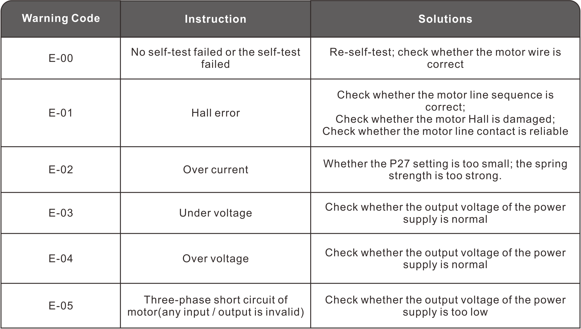
- The normal startup of the controller is "00:00" and "e-00"
alternately displayed. Press and hold the controller "close / turn up" for 2 seconds, and the track gate operates in the
direction of closing. The controller scrolls from left to right to
display "0 0 0 0", and the buzzer sounds rhythmically. When the
motor runs to the closing limit, the controller displays static "0
0 0 0" and the buzzer stops ringing. At this time, the closing
self-test is completed.
- After the closing self-test is completed, press and hold the
controller "open / down" for 2 seconds, and the track gate operates in the opening direction. The controller
scrolls from left to right to display "0 0 0 0", and the buzzer
sounds rhythmically. When the motor runs to the opening limit, the
controller buzzer sounds for a long time. At this time, the opening
self-test is completed, and the gate can operate normally.
Step 3: Adjust The Horizontal And Vertical Position Of The Gate
Lever- The pole exceeds 90 degrees after driving to the position (adjust
the P-9 parameter to a large scale); The pole is less than 90 degrees(reduce the P-9 parameter).
- Close to the position where the pole is higher than the horizontal
position (reduce the P-6 parameter); The pole is below the level position (increase P-6).
Note: 1. Judge whether the horizontal position of the fence pole
and the advertising gate is in place (the pole contacts the ground
motor will stop immediately (if the motor is still rotating after
it is in placeincrease the P-6 parameter until the motor does not
rotate after the pole reaches the ground.After debugging the parameters, the switch needs to be operated to
see the position change.Key Operation
The controller has four keys, namely "on / down", "return / stop",
"set / save" and "off / up". You can set various parameters of the main board through these four keys.Shortcut Key Operation
- Press the "on / down" button once in the mode without inserting the
motor cable to display the software version number; Press the "off / up" key once to display the
software date.
- In the normal working mode, under the display time page of the
digital tube, short press "set / save" once to display the current value, short press "set / save" for the second time to
display the change rate of hall, and short press "set / save" for
the third time to display the internal voltage value of the
controller; Short press "set / save" for the fourth time to display
the power supply voltage value;
Key Function Description
Set / save key: enter the setting state and save the setting value.
On / down key: press this key to open the gate in normal working
state. After entering the setting state, you can use this key to add menu items or adjust the setting value
upward. In the parameter setting state, short press to add one each
time. Press and hold continuously until the maximum value is
reached, and then add from the minimum value.
Off / up key: press this key to close the gate in normal working
state. After entering the setting state, you can use this key to reduce menu items or adjust the setting value
downward. In the parameter setting state, short press to subtract
one at a time. Long press to continuously decrease to the minimum
value and then decrease from the maximum value.
Return / stop key: in normal working state, press this key to stop
the brake. In the setting state, you can exit the setting state or return to the previous menu.
Parameter Menu
Operating Instructions
You can enter the parameter setting state by long pressing the "set
/ save" button for 3 seconds, and the LED will display "P-X". Select the menu items by pressing the two
buttons "on / down" and "off / up" for a short time or a long time.
Short press to increase or decrease one item at a time, and long
press to increase or decrease continuously. Press the "set / save"
key again to enter the setting of the specified item, and the
"return / stop" key to exit the setting. After setting the
specified parameters, you must press the "set / save" key to
confirm it. The parameters set by pressing the "return / stop" key
will not take effect. If there is no key within 45 seconds, the
buzzer on the control panel will sound for a long time, exit the
setting state and return to the normal working state.Parameter Command Value Table

- For all places involving angles, the closing position is 0 degrees.
- When the power supply voltage is too large (> 27V) or too small
(< 18V), the controller will automatically protect and give an alarm.when the controller is protected, the
motor, light box, ground sensor and other equipment will not work.
Remote Control Function
- Remote control pairing: long press the controller "set / save" for
three seconds, find the P-F item, and press the "set / save" again to display "000". At this time, press any
key of the remote control. At this time, after the controller makes
a long sound, the display changes to P-F, indicating that the
remote control is matched successfully.
- Clear the remote controller: long press "set / save" on the main
board for three seconds, find the P-F item, press "set / save" again to display "000", adjust the value to 253,
and press "set / save" again. At this time, after the main board
makes a long sound, the display changes to P-F, and all remote
controllers will be cleared.
- Fleet mode: long press "set / save" on the controller for three
seconds, find item p-8, and then press "set / save" to display "0", adjust the value to 4, and then press "set / save"
to exit the menu; After the road gate is opened in place, press the
stop button of the remote controller for more than 2 seconds, and
the fleet mode will start; To turn off the fleet mode, just press
the off key of the remote controller.
Parameter Transfer Steps
Step 1: debug a template
Step 2: connect the template with the new controller
Step 3: power on the new controller
Step 4: long press the " down" button of the template, and check
the "s -- s" displayed on the new controller, then the parameter transfer is successful
Common Problems And Solutions
Solution: check whether the left-right rotation mode of the P-D
motor matches the current motor or not (you can re power on the controller after changing the parameters and
conduct self-test again. Please refer to "Chapter 1, subsection 6,
step 2" for whether the self-test of the track gate is normal)Solution: adjust the controller menu P-9 or P-6 parameters (refer
to the parameter table for menu functions)Set the P-18 parameter of the controller to 1. If the relay is
opened or closed once, it indicates that it has been opened / closed in place
Pay attention to observe whether the motor stops when the gate
lever is in place, which means it is in place. If the gate lever is in place and the motor is still running, it is
necessary to change the P-6 or P-9 parameters.
In the process of switching on and off, the nixie tube will have a
dynamic "1" display. If the nixie tube display returns to the time interface, it indicates that it has been in
place.
Solution: A. check whether the P-C parameter turns on the
resistance rebound (if the controller parameter is greater than 100, the resistance rebound function fails)Solution: increase the value of P-C rebound function parameterSolution: increase the stability value of P-3 in placeError codes and Solutions
| BR-110 | BR-110F | BR-110BY | BR-110L | BR-110H |
 Straight arm version Straight arm version
Lifting time: 3s 6s |  High speed version High speed version
Lifting time 1.5s | 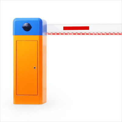 LED ligtht version LED ligtht version
Lifting time: 3s 6s | 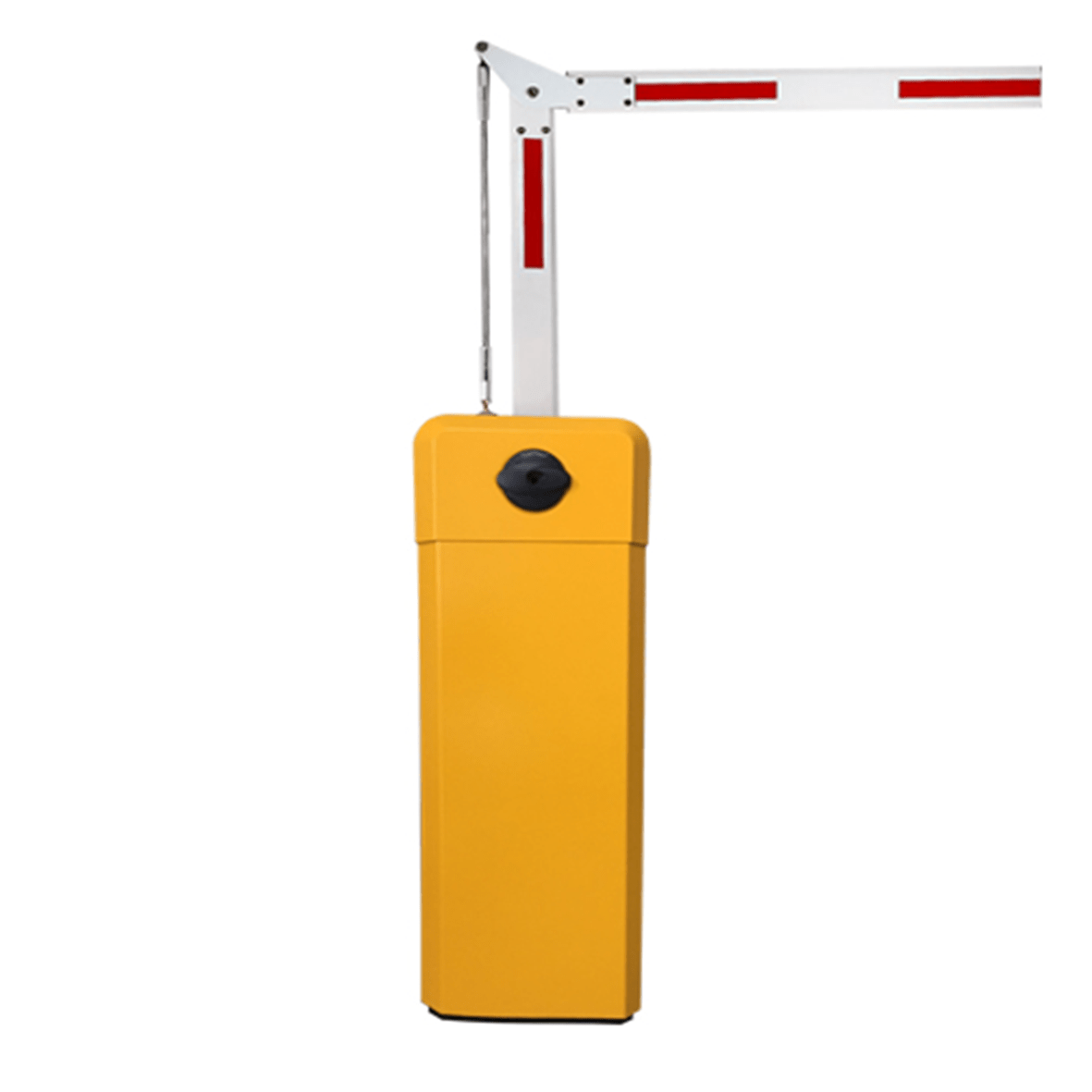 90° Folding arm version 90° Folding arm version
Lifting time: 3s 6s | 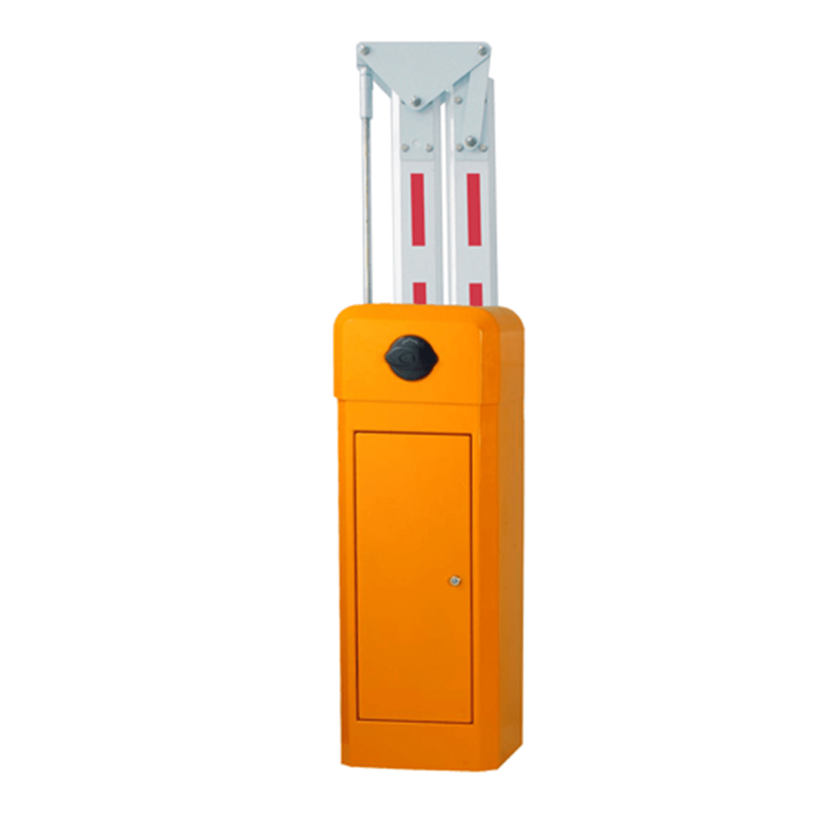
180° Folding arm version Lifting time: 3s 6s |
| BR-121 | BRDC-110 | BDC-1 | BRC-433R | BRC-443T |

Fence arm version Lifting time: 6s | 
DC power economy version Lifting time: 1.2-5s |  |  |  |


